Fans and fan connections
 |
Warning:
Only an authorized electrician may perform the electric connections.
|
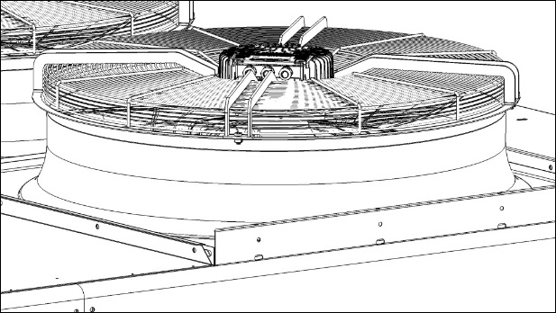
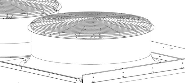
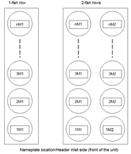
Fan packages with EC motors
 |
Warning:
EC-fans: Electrical load (>50 μC) between mains wire and protective earth connection after switching of the supply when switching multiple devices in parallel. Electric shock, risk of injury. Ensure that you have sufficient protection against accidental contact. Before working on the electrical connection, short the connections to the mains supply and PE. EC-fans: Terminals and connections have voltage even in a unit that is shut off. Electric shock. Wait for five minutes after disconnecting the voltage at all poles before opening the device.
|
 |
Warning:
EC-fans: High temperature at the electronics enclosure. Danger of burn injuries. Ensure that you have sufficient protection against accidental contact. |
The fan package is suitable for 380...420 V 50/60 Hz electric network.
The protection glass is IP54, as the option fans are prewired to the safety switch (IP65).
Fan motors/electronics are over temperature protected.
Fans installed in horizontal position
Route the cable in a loop (water trap).
Fans installed in upright position
When routing the cable, ensure that you arrange the screwed cable glands at the bottom. Always route the cables downwards.
The fan units are preset at the factory to the required fan speed. Ask the condenser/liquid cooler manufacturer about the technical data of the fan motors.
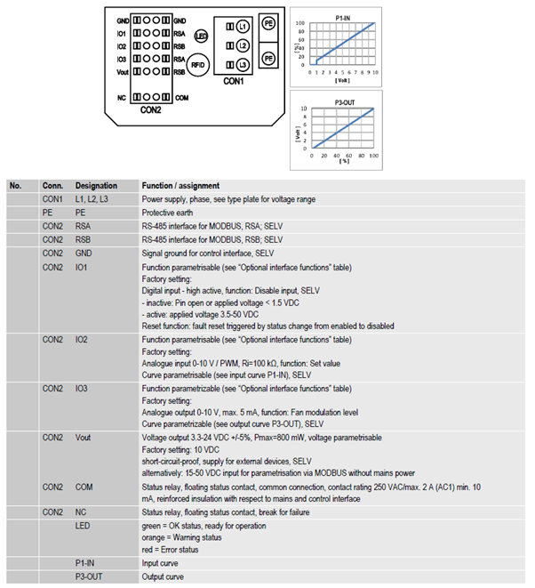
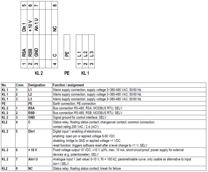
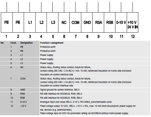
| Fan, Pe = 2550 W (980 RPM) | Fan Pe = 630 W (max 610 RPM) | |||
|---|---|---|---|---|
| Noise level | RPM | ~Vdc | RPM | ~Vdc |
| TD | 980 | 10 | ||
| TY | 890 | 9,1 | ||
| SD | 781 | 8,0 | ||
| SY | 695 | 7,1 | ||
| LD | 612 | 6,2 | 610 | 10 |
| LY | 560 | 5,7 | 568 | 9,3 |
| QD | 511 | 5,2 | 519 | 8,5 |
| QY | 440 | 4,5 | 447 | 7,3 |
| LD | 385 | 3,9 | 391 | 6,4 |
| LY | 345 | 3,5 | 350 | 5,7 |

Fan packages with IEC motors
The fans are direct driven axial fans. The fan motors are 3-phase squirrel-cage motors built according to the IEC standards, designed for outdoor use and provided with condensing water outlets, shaft seals and self-lubricating bearings. The motors are suitable for 400 V/690 V 50/60 Hz electric network. Their protection class, except for condensing water outlet, is IP54 or IP55 (excluding waterholes) as a standard. The motors are prewired to the service switches (IP65).
Ask the liquid cooler manufacturer about the technical data of the fan motors.
If the unit stands inactive for a long period, we recommend you to anticondensate the heater installation to the fan motors.


