
Turning and lifting unit

|
Warning:
Before lifting the unit, check its weight from the transport documents or from the product nameplate and make sure that the lifting device, crane or truck is appropriate.
Do not stand under the unit when it is hanging.
|


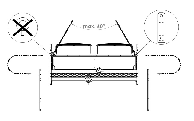
Only qualified personnel using approved lifting equipment is allowed to carry out lifting operations.
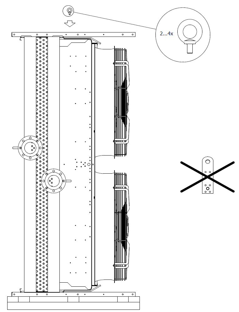
When lifting the unit, use all lifting points in the direction of lifting. Do not mix the lifting points of vertical and horizontal position.

The AlfaSolar L/SR™ units are transported in vertical position as standard. Turn the units for horizontal installation (vertical air flow) to the correct position at installation.
To turn a vertical air flow unit, which is packed in an upright position, into operating position:
-
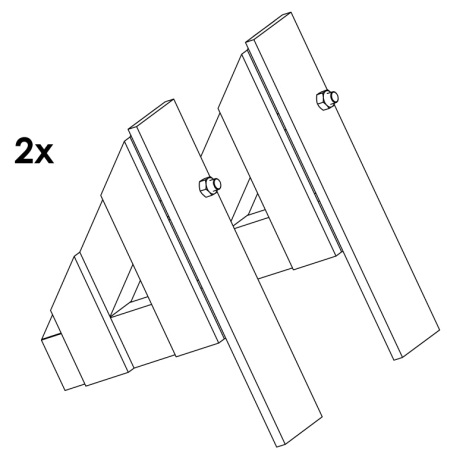
Fix the lifting/turning lugs into the fixing points on the sides of the
unit.
CAUTION: Ensure that the lugs are tightly fixed.
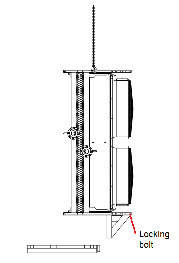
- Hang the unit by crane from the lifting/turning lugs so that the lifting chain tightens but the unit remains on ground.
- Remove the unit from the transport pallet.
-
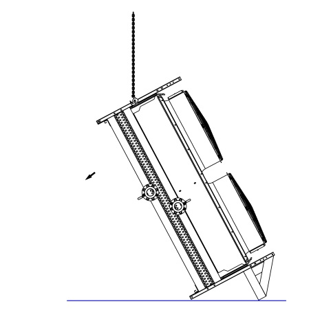
Lift up the unit ca 0.5 m from the ground.
-
Put down the unit carefully so that it turns around the turning leg, to the
direction of the centre of gravity. Drive the crane into the turning position
and put the unit down slowly into horizontal position.
-
Remove the lifting/turning lugs from the unit.
- Remove the turning supports.
- Remove the transportation legs.
-
Hang the unit from the lifting points of the vertical air flow model. Adjust
the legs of the vertical model to the correct installation height.
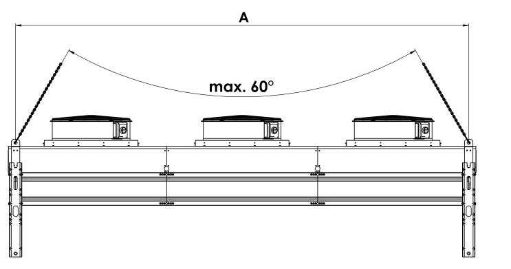 CAUTION: The minimum length of a lifting chain, when no lifting channel is used, is the distance of the lifting points. For LM™ and LD™ models, see the table LM™ and LD™ models: Distance between lifting points. We recommend using a lifting channel. Check the unit weight from the product nameplate.
Table 1. LM™ and LD™ models: Distance between lifting points Unit LM™
Distance between lifting points A mm Unit dry weight kg Unit LD™
Distance between lifting points A mm Unit dry weight Unit LD™
Distance between lifting points A mm Unit dry weight 1A-3 1400 259 2A-3 2800 689 5B-4 5400 1702 1A-4 1400 279 2A-4 2800 748 5B-3 5400 1898 1A-5 1400 300 2A-5 2800 809 5B-5 5400 2094 1A-6 1400 320 2A-6 2800 870 5B-6 5400 2290 1B-3 1800 282 2B-3 3600 775 5C-4 6300 1874 1B-4 1800 308 2B-4 3600 853 5C-3 6300 2102 1B-5 1800 334 2B-5 3600 932 5C-5 6300 2331 1B-6 1800 360 2B-6 3600 1010 5C-6 6300 2560 2A-3 2800 408 2C-3 4200 845 6A-3 5600 1761 2A-4 2800 449 2C-4 4200 937 6A-4 5600 1944 2A-5 2800 489 2C-5 4200 1028 6A-5 5600 2127 2A-6 2800 530 2C-6 4200 1120 6A-6 5600 2310 2B-3 3600 463 3A-3 1400 945 6B-3 7200 2024 2B-4 3600 516 3A-4 1400 1037 6B-4 7200 2259 2B-5 3600 568 3A-5 1400 1128 6B-5 7200 2495 2B-6 3600 620 3A-6 1400 1220 6B-6 7200 2730 3A-3 1400 567 3B-3 1800 1077 6C-3 4200 & 8400 2226 3A-4 1400 628 3B-4 1800 1195 6C-4 4200 & 8400 2501 3A-5 1400 689 3B-5 1800 1312 6C-5 4200 & 8400 2775 3A-6 1400 750 3B-6 1800 1430 6C-6 4200 & 8400 3050 3B-3 1800 655 3C-3 2100 1178 7A-3 4200 & 7000 2019 3B-4 1800 733 3C-4 2100 1315 7A-4 4200 & 7000 2233 3B-5 1800 812 3C-5 2100 1453 7A-5 4200 & 7000 2446 3B-6 1800 890 3C-6 2100 1590 7A-6 4200 & 7000 2660 4A-3 2800 736 4A-3 2800 1224 7B-3 5400 & 9000 2326 4A-4 2800 817 4A-4 2800 1346 7B-4 5400 & 9000 2601 4A-5 2800 899 4A-5 2800 1468 7B-5 5400 & 9000 2875 4A-6 2800 980 4A-6 2800 1590 7B-6 5400 & 9000 3150 4B-3 3600 847 4B-3 3600 1399 - - - 4B-4 3600 951 4B-4 3600 1556 - - - 4B-5 3600 1056 4B-5 3600 1713 - - - 4B-6 3600 1160 4B-6 3600 1870 - - - 5A-4 4200 885 4C-3 4200 1399 - - - 5A-3 4200 987 4C-4 4200 1531 - - - 5A-5 4200 1088 4C-5 4200 1714 - - - 5A-6 4200 1190 4C-6 4200 1897 - - - 5B-3 5400 1038 5A-4 4200 1482 - - - 5B-4 5400 1169 5A-3 4200 1635 - - - 5B-5 5400 1299 5A-5 4200 1787 - - - 5B-6 5400 1430 5A-6 4200 1940 - - - CAUTION: The minimum length of a lifting chain, when no lifting channel is used, is the distance of the lifting points. See the table SRM™ and SRD™ models: Distance between lifting points. We recommend using a lifting channel. Models outside this list (E), non-standard models and copper coil (Cu…Cu): Check the unit weight from the product nameplate.Table 2. SRM™ and SRD™ models: Distance between lifting points Unit SRM™
Distance between lifting points A mm Unit dry weight kg Unit SRD™
Distance between lifting points A mm Unit dry weight (ɸ914)/ (ɸ1200) kg Unit SRD™
Distance between lifting points A mm Unit dry weight (ɸ914)/ (ɸ1200) kg 1A-3 1400 360 2A-3 2800 820/- 5B-4 5400 2130/2600 1A-4 1400 440 2A-4 2800 950/- 5B-3 5400 2400/2870 1A-5 1400 470 2A-5 2800 1020/- 5B-5 5400 2620/3090 1A-6 1400 490 2A-6 2800 1080/- 5B-6 5400 2830/3300 1B-3 1800 390 2B-3 3600 960/1160 5C-4 6300 2310/2780 1B-4 1800 480 2B-4 3600 1110/1300 5C-3 6300 2620/3080 1B-5 1800 510 2B-5 3600 1200/1390 5C-5 6300 2870/3330 1B-6 1800 540 2B-6 3600 1280/1480 5C-6 6300 3120/3580 2A-3 2800 560 2C-3 4200 1040/1230 6A-3 5600 2110/- 2A-4 2800 660 2C-4 4200 1190/1390 6A-4 5600 2370/- 2A-5 2800 710 2C-5 4200 1300/1490 6A-5 5600 2580/- 2A-6 2800 750 2C-6 4200 1400/1590 6A-6 5600 2770/- 2B-3 3600 620 3A-3 1400 1130/- 6B-3 7200 2530/3090 2B-4 3600 740 3A-4 1400 1290/- 6B-4 7200 2840/3410 2B-5 3600 800 3A-5 1400 1390/- 6B-5 7200 3100/3670 2B-6 3600 850 3A-6 1400 1490/- 6B-6 7200 3360/3920 3A-3 1400 760 3B-3 1800 1340/1630 6C-3 8400 2750/3300 3A-4 1400 880 3B-4 1800 1530/1820 6C-4 8400 3100/3660 3A-5 1400 950 3B-5 1800 1660/1950 6C-5 8400 3410/3960 3A-6 1400 1010 3B-6 1800 1790/2070 6C-6 8400 3700/4260 3B-3 1800 850 3C-3 2100 1450/1740 7A-3 4200 2420/- 3B-4 1800 1000 3C-4 2100 1660/1940 7A-4 4200 2720/- 3B-5 1800 1080 3C-5 2100 1810/2100 7A-5 4200 2950/- 3B-6 1800 1170 3C-6 2100 1960/2240 7A-6 4200 3180/- 4A-3 2800 970 4A-3 2800 1460/- 7B-3 5400 2910/3570 4A-4 2800 1120 4A-4 2800 1650/- 7B-4 5400 3270/3930 4A-5 2800 1210 4A-5 2800 1790/- 7B-5 5400 3570/4230 4A-6 2800 1300 4A-6 2800 1920/- 7B-6 5400 3860/4520 4B-3 3600 1100 4B-3 3600 1740/2120 - - - 4B-4 3600 1270 4B-4 3600 1970/2350 - - - 4B-5 3600 1390 4B-5 3600 2140/2520 - - - 4B-6 3600 1500 4B-6 3600 2310/2690 - - - 5A-4 4200 1170 4C-3 4200 1890/2260 - - - 5A-3 4200 1340 4C-4 4200 2150/2520 - - - 5A-5 4200 1450 4C-5 4200 2350/2720 - - - 5A-6 4200 1560 4C-6 4200 2540/2920 - - - 5B-3 5400 1330 5A-4 4200 1780/- - - - 5B-4 5400 1530 5A-3 4200 2010/- - - - 5B-5 5400 1670 5A-5 4200 2180/- - - - 5B-6 5400 1810 5A-6 4200 2340/- - - -